Hi guys,
My "famous" ST3000DM001 failed last week, and since then, I'm reading every forum and watching lots of data recovery videos (many thanks Jared, for your responses on YouTube ), and I'm begging to get quite a good picture regarding the recovery process. The subject started to captivate me, and it would make a nice learning experience.
Most likely the drive is stuck in the BUSY state. Spins up, the heads seek a few times, no strange noise, but the computer POST takes a lot of time, then the computer finally boots from an SSD, but the case HDD led remains ON permanently(I guess this is a cheapo way to confirm the issue, without professional tools like pc3k)
Now I was considering to try shorting the read channel. If I succeed this operation, will the drive be accessible from the SATA port as well? or only from the serial terminal connection? I understand that this is not a permanent fix and it will be required to be done every time I power on the drive... but can it work?
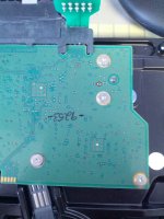
Meanwhile, I have removed the PCB, and I'm trying to identify the read channel.
I couldn't find pictures with exactly the same PCB model, but it seems to be very close to the one in the video above, with the shorting foil https://www.youtube.com/watch?v=_Mrvo87WvF8
Can you please confirm that I have identified them correctly here? Or is it the reverse?
I know I should search for the controller datasheet, but I don't want to ruin that thermal pad.


I need to mention that I have successfully cleaned the black residue surrounding the holes using a bit of scotch tape, they are now gold and shiny )
)
My "famous" ST3000DM001 failed last week, and since then, I'm reading every forum and watching lots of data recovery videos (many thanks Jared, for your responses on YouTube
Most likely the drive is stuck in the BUSY state. Spins up, the heads seek a few times, no strange noise, but the computer POST takes a lot of time, then the computer finally boots from an SSD, but the case HDD led remains ON permanently(I guess this is a cheapo way to confirm the issue, without professional tools like pc3k)
Now I was considering to try shorting the read channel. If I succeed this operation, will the drive be accessible from the SATA port as well? or only from the serial terminal connection? I understand that this is not a permanent fix and it will be required to be done every time I power on the drive... but can it work?
Meanwhile, I have removed the PCB, and I'm trying to identify the read channel.
I couldn't find pictures with exactly the same PCB model, but it seems to be very close to the one in the video above, with the shorting foil https://www.youtube.com/watch?v=_Mrvo87WvF8
Can you please confirm that I have identified them correctly here? Or is it the reverse?
I know I should search for the controller datasheet, but I don't want to ruin that thermal pad.


I need to mention that I have successfully cleaned the black residue surrounding the holes using a bit of scotch tape, they are now gold and shiny


