Toshiba USB to SATA Guide

LarrySabo

Member
Jared":pyd45q06 said:
[post]8637[/post] Maybe I should box up and mail you my used up ones as a way of recycling them.
No thanks. :eek: They usually don't leave the clean chamber so I haven't had any issues (that I can attribute to the gloves).
 
G3448A ----------> G003138A

just tried to swap with G003138A sata pcb, i can confirm you that it doesn't work
Drive heads do click like crazy and very loud.
G003138A MCU version match with G3448A MCU, however these pcb swap doesn't work.
 

Jared

Administrator
Staff member
michael chiklis":37hzxjt2 said:
G3448A ----------> G003138A

just tried to swap with G003138A sata pcb, i can confirm you that it doesn't work
Drive heads do click like crazy and very loud.
G003138A MCU version match with G3448A MCU, however these pcb swap doesn't work.

Thanks for the confirmation (or should I say de-confirmation) :D

I left it in there marked as "doesn't work" just in case it's one of those odd things where it works in some cases but not others type of thing.
 
Jared":3j7p6dmf said:
[post]4820[/post] G3448A ----------> G003235B or G003138A
G003309A -------> G003138A (doesn't seem to work)
G003296A -------> G003235B

ok, but you have written (doesn't seem to work) on the wrong line.

it should be as following:
G3448A ----------> G003235B or G003138A (G003138A doesn't seem to work)
G003309A -------> G003138A
G003296A -------> G003235B

Today afternoon i will try with G003235B pcb if does work as equivalent sata of G3448A and i'll let you know.
 
I've played a little in last days with these toshiba pcb :)
I was able to read rom from native usb pcb in serial mode with MRT utility, it takes long time (1 hour) but it's the best way for those people who don't feel safe using hot air to pull out rom chip from board or if they don't have a hot air station.
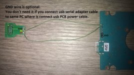
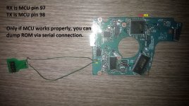
You just need to solder two wires (Tx - Rx) between usb pcb and a COM adapter (i used a seagate COM because it was already broken).
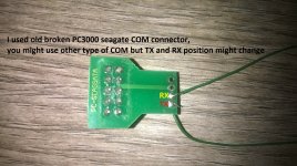
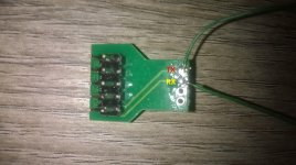
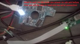
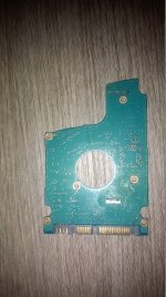
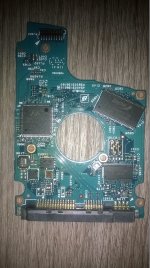
Toshiba COM pic1.jpgToshiba COM pic2.jpgCOM + PCB pic3.jpgCOM + PCB pic4.jpgPCB + COM + serial adapter pic5.jpg

It's important to respect timings or it will not work.
When you power on usb pcb, white led will power on for 20 seconds, then it will power off.
Since that moment you have to wait 7 minutes before that Toshiba utility will begin to communicate with microcontroller
Total time you need to wait until MCU will begin to communicate in serial mode since you power on pcb is 7m 20s

It means that you have to wait at least 7m 20s, if you try to read ROM before that time then it just will refuse to read rom and toshiba utility will send message 'error reading rom'
if that happens don't worry, just continue to wait, count will not reset.
If serial rom is reading properly, you will see serial adapter yellow led (RX) power on and red led (TX) blinking.

Reading speed in serial mode is very slow on toshiba drives (9600 bps), this means that it will take about 1 hour to get rom code dumped.
 
Unfortunately there isn't a way to write rom on donor sata pcb via serial mode, but i'll explain you how to write it without taking off chip from donor pcb by using eprom programmer.
This task is hard, you'll need good soldering skills with classic soldering iron, steady hand, good magnifying glass and time, but at least you can do it without unsoldering rom chip from sata pcb.
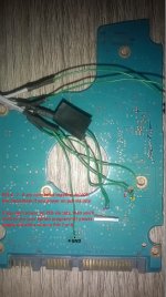
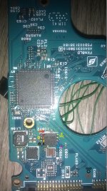
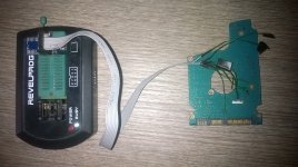
Need to solder 6 thin wires, or just 5 wires due to fact that it will not be necessary to apply on rom Vcc power with your eprom programmer, just power on sata pcb by using computer sata cables to easily supply Vcc on rom chip.

wp_20171012_18_14_26_pro.jpgwp_20171012_18_15_22_pro.jpgwp_20171012_16_41_59_pro.jpgwp_20171012_16_39_15_pro.jpgwp_20171012_17_19_50_pro.jpg

Vcc is ROM pin 8, pin 3 and 7 are natively jointed together on board to pin 8.
This means that pins 3 - 7 - 8 are in common.
 
Top